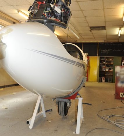
Two people can bring the fuselage to the stand, and that the stand is very stable, making it easy to work on the glider.
Holger Weiztel
The manual advises test-running the engine only when the glider is rigged, tied down, and a pilot is in the glider [need citation]. The manual doesn't give any reasons, but there are clearly some advantages:
At least one pilot has been killed while running engine without rigging; others have had the fuselage tip over or "crawl" into the trailer, resulting in considerable damage and some injury. None of the pilots were ASH 26 E pilots, to my knowledge.
Running the engine is always a serious business, even with the glider rigged, and more so when it isn't.
Given all that, why would anyone want to avoid rigging the glider? Sometimes, it is very convenient to do it where you keep the glider to avoid a long trip to the airport, or do it where you have all the tools and instruments needed to fix a problem.
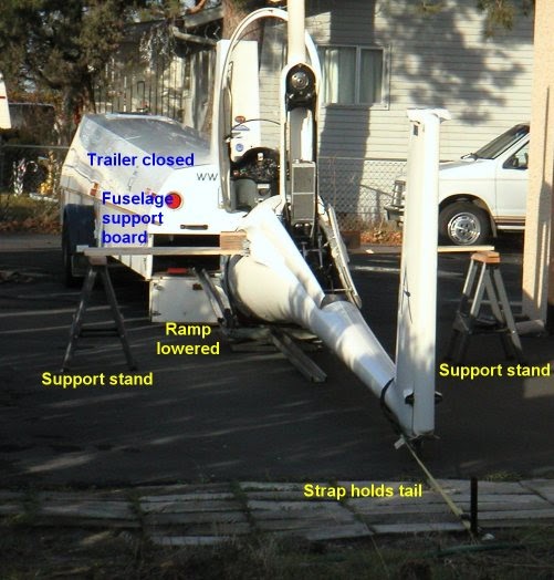
Here is the procedure I use for running the engine with the fuselage on the trailer ramp. I don't claim it's as safe as doing it with a fully rigged glider, but I believe it's "safe enough" for the three or four times a year I do it. I use a written checklist so I don't forget any steps.
Engine running checklist:
Comments on these steps:
I've always stood outside the cockpit while running the engine this way, but it might be even safer to sit in the cockpit while doing this, while carefully checking the area for other people.
Another way of proceeding...(from Belgium)
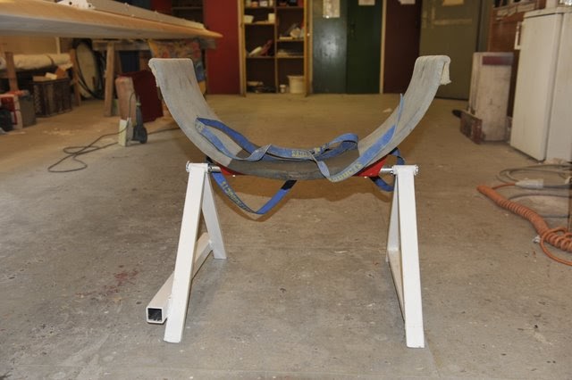
The concept I used was based on the one described here above. My fear was that the fuselage could fall on the right or left side on the ground because of the engine vibration level. So I developed a strong wooden structure I could introduce inside the fuselage where the wings should normally come in. The two vertical beams are screwed to the horizontal beam.
Here a picture of the system.
Of course, I strongly recommend to run the engine in static mode with the help of a friend who can look around for security aspects. My experience of this setup is that the fuselage is very stable.
Pay attention that I put some concrete blocks before the wheel and that the glider is up the hill. There is a strong slope before the house that perhaps is not seen on these pictures. In addition, I did run the engine at about 4000 rpm not higher. The objective was only to warm up the engine in winter period without going to the airfield.
The Roeger hook, and it's variations, enable a clean jettisoning of the canopy. The hook holds the rear of the canopy to fuselage until the front of the canopy has lifted high enough for the air flow to lift it off the glider. Without this hook, the canopy may "jump" backwards, hit the pilot and injure him, or impede and slow his escape.
Here's an article on the DG site, including videos of some of the testing done by Prof. Roeger. Scroll down half-way for the research project report.
Newer ASH 26 Es are delivered with a Roeger Hook already installed.If you have an older ASH 26 E, please install a Roeger hook for your safety!Schleicher has a kit for this, and the labor wasn't too expensive when I had mine installed in 1998. The picture shows the plunger installed on the canopy, and catch spring installed in the fuselage.
Basic oil system data
Oil consumption rate:
Oil tank capacity:
Oil remaining when the Ilec oil warning light illuminates:
Based on the above numbers, we can calculate the engine can be operated at max RPM (6900 RPM) for about 2 hours, 45 minutes before the oil level in the oil tank is too low (don't count on it if you haven't tested YOUR glider!). This is true, whether climbing at full throttle and 6900 RPM, or cruising at part throttle and 6900 RPM, because the oil consumption is independent of the amount of fuel used.
This "power independent" oil consumption has important consequences if you have the wing fuel tanks (bags) installed:
Measuring the oil consumption
What's wrong with the manual's method?
The manual gives an approximate oil consumption for each liter of fuel. This number seems close to what people measure if they use the engine only for the launch. These are pilots that push or tow their gliders to the takeoff point instead of taxiing. Low rpm engine use apparently uses fuel at a different liters/revolution than full power, so pilots that taxi get very variable, essentially worthless, measurements indicating not enough oil is being used.
Why use a revolution counter?
The oil pump on our engine is a "positive displacement" type, meaning the amount of oil pumped is directly proportional to the number of revolutions. In other words, 10 revolutions pumps 10 times as much oil as one revolution.
Our pump is driven directly from the engine, so the amount of oil pumped is directly related to the number of engine revolutions. The factor is 0.5 ml per 1000 revolutions; e.g., running the engine at 3500 rpm for 2 minutes (7000 revolutions) should pump 3.5 ml of oil. By comparing the revolutions mearsured with the counter to the amount of oil actually removed from the oil tank, we can determine if the engine is consuming the correct amount of oil. Too much oil consumed may indicate a leak in the oil tank, or in it's oil line and it's connections to the pump; too little oil consumed may indicate the pump is not working properly, or has a blocked oil line going to the engine.
The factory does provide a method for measuring the oil consumption in a maintenance Instruction ("Oil Consumption" Issue 1) available on the Schleicher website. Basically, you run the engine at a constant rpm for several minutes, then measure the amount of oil removed from the oil tank.
[Nov 2008 - bumper]
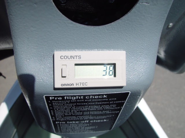
I installed Eric's rev (revolution) counter on my ship. The counter is from Digi-Key (part number Z865), and is an Omron H7EC-NV-B. [see below for background on why a revolution counter is used]
If you choose to mount the counter in this location, I suggest favoring the bottom edge as shown. The hole was laid out with a fine tip marker and then cut out with a Dremel tool using a 1/8" carbide burr - - carefully! Corners were squared up with a file. The face plate lip of the counter is not all that wide, so the hole can't be much oversize.
With power off, I removed plug on the rear of the ILEC. If you haven't done this before, there's a small spring latch on each side of the DB29 plug, one pushes up and the other pushed down to release. Then I stripped back the heat shrink cable sheath for several inches to make it easier to splice in the two wires needed for the counter (signal and ground).
To save you the trouble of taking apart the plug to check colors and pins (g) - - there are no duplicate colors used in the wiring harness. The signal wire is a smaller solid black wire (pin 21) and ground is a larger diameter solid blue wire (pin 15). Strip a short length of insulation from each, offsetting so the splices will not be adjacent to each other. Then solder wires to each and insulate with tape, I used self-vulcanizing rubber tape. Wire splice to small black wire goes to terminal #1 on the counter, wire spliced to the blue wire (ground) will go to terminal #2 of the counter.
Eric suggested it would also be an option to mount the counter on the seat pan in a convenient spot and splice into the cable as it goes through that area. I think the under panel location is pretty good though, with just one warning! If you use the "wallet trick" to remove and replace your canopy (that's where you put a wallet on the lower console and close the canopy on it to make it easier to remove) be careful to keep the wallet away from the forward edge of the lower console top as the counter will hit the wallet. No need to ask me how I know this, but at least I didn't force the issue and break anything.
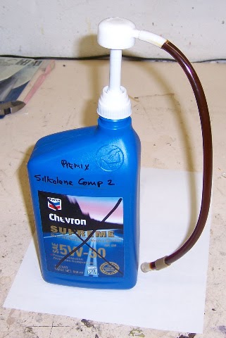
Again, using Eric suggestion, I cut off most of the end of a 60 ml irrigation syringe. Then overfilled the oil tank and pushed the nose of the modified syringe as far as possible into the tank to suck out as much as possible to get the oil to the correct "calibrated" full level. After running the engine, it should be a simple matter to add a measured amount of oil with the syringe to overfill the tank, then remove as much as possible with the short nose syringe and subtract the amount of removed oil from the previous added amount to determine oil used.
Per Eric, the engine should use about 0.5 ml of oil per 1000 revolutions, so 70,000 total count should see 35 ml of oil used.
Page 5 of 10